
Concepts
Terminology
The way that sound propagates is impacted by objects that it collides with in a number of ways. Simply stated the interaction between sounds and objects may result in Obstruction, Occlusion, or Exclusion. Diffraction of sounds also occurs when they bend around obstacles or spread out as they pass through openings.
Obstruction:
The direct path of the sound is blocked, but you can hear the indirect reflections and diffraction of the sound around obstacles.
Occlusion:
The direct path and reflections of the sound are blocked but you may hear the sound transmitting through other materials.
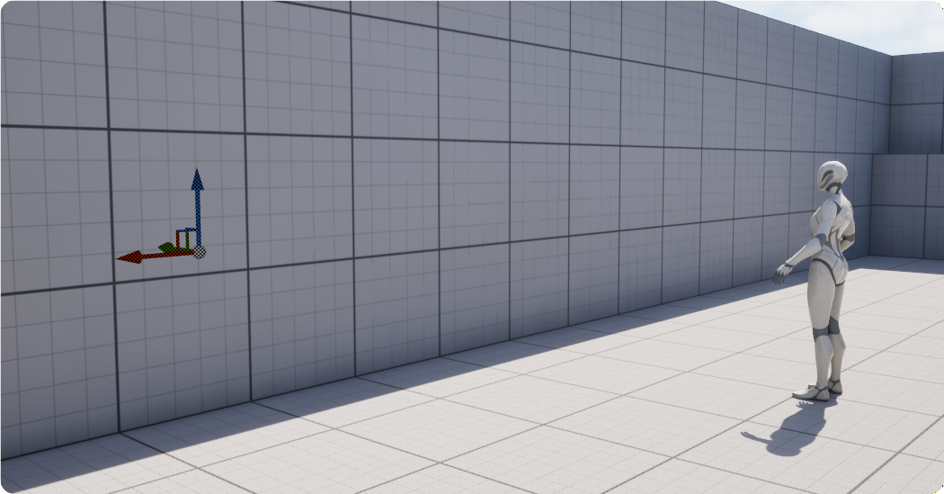
Exclusion:
The direct path of the sound is clear, but reflections are blocked.
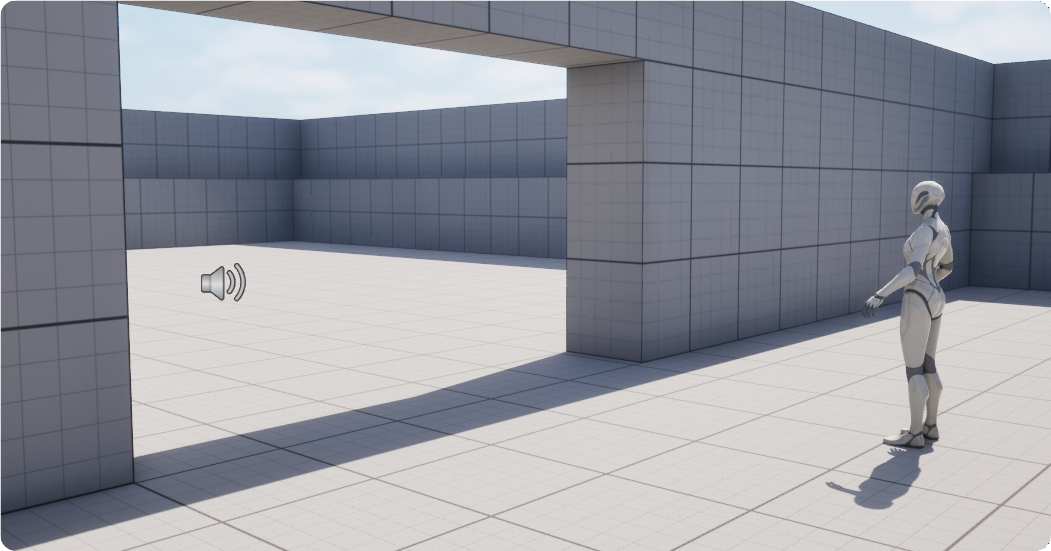
Diffraction:
Diffraction of sound is where sound waves bend around obstacles or spread out after passing through narrow openings.
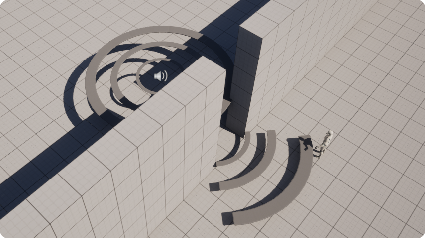
The current version of the SweejTech Propagation system is focussed on Obstruction.
The native Unreal Audio approach
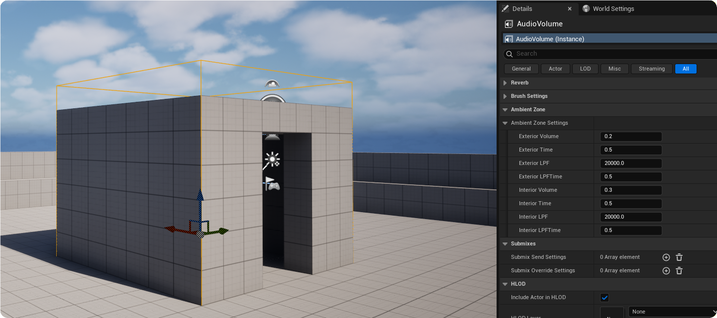
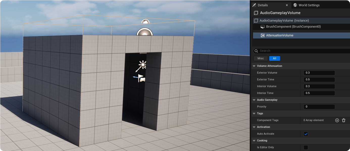
The native Unreal Engine systems for occlusion and obstruction work on a room based or direct path-based model. Room based obstruction utilizes Audio Volumes (via Ambient Zones) or Attenuation Volume components on Audio Gameplay Volumes.
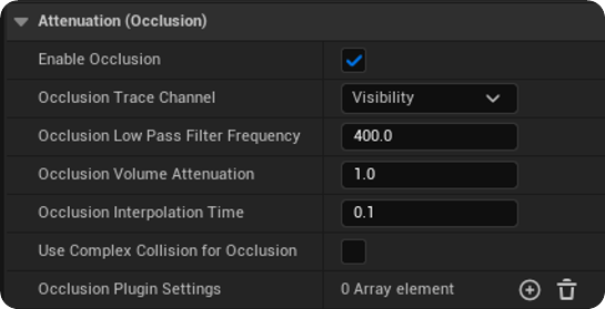
Direct path obstruction is enabled through the Attenuation options of a sound where volume attenuation and a low pass filter can be applied when the direct path on a given trace channel between the audio source and listener is obstructed.
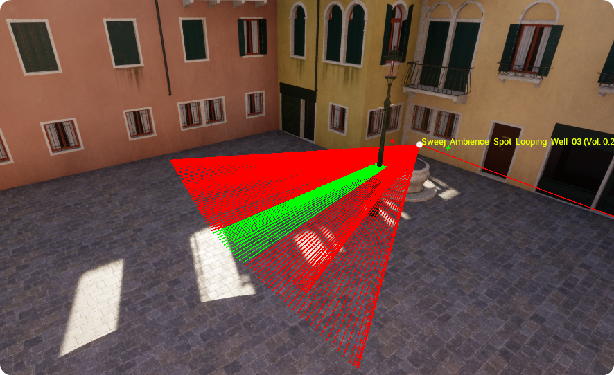
Although there is an interpolation time for any obstruction to take effect the results remain quite binary, sounds are either fully obstructed or not. For example, the sound source behind the lamppost in the example below will have the full occlusion settings applied when the path to the listener is obstructed by the thin metal pole which feels unrealistic.
Note: The following section shows debug displays and values that can be observed using the Obstruction Inspector see Quick Reference for a quick guide to the Obstruction Inspector.
The SweejTech GPU Ray Trace System
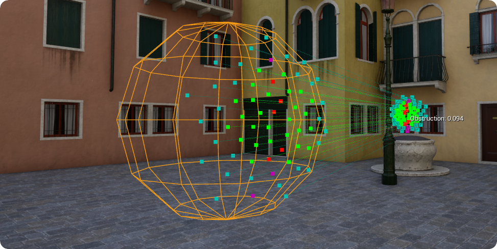
The SweejTech Propagation system avoids this binary approach to obstruction by utilizing a number of points on a sphere around both the listener and source, then generating ray traces between them. The traces are run on the GPU for highly performant results, even with multiple sound sources.
Attenuation & Obstruction
SweejTech Propagation works in conjunction with Unreal Engine's attenuation system. Obstruction is only active when within the Falloff Distance of a sound actor.
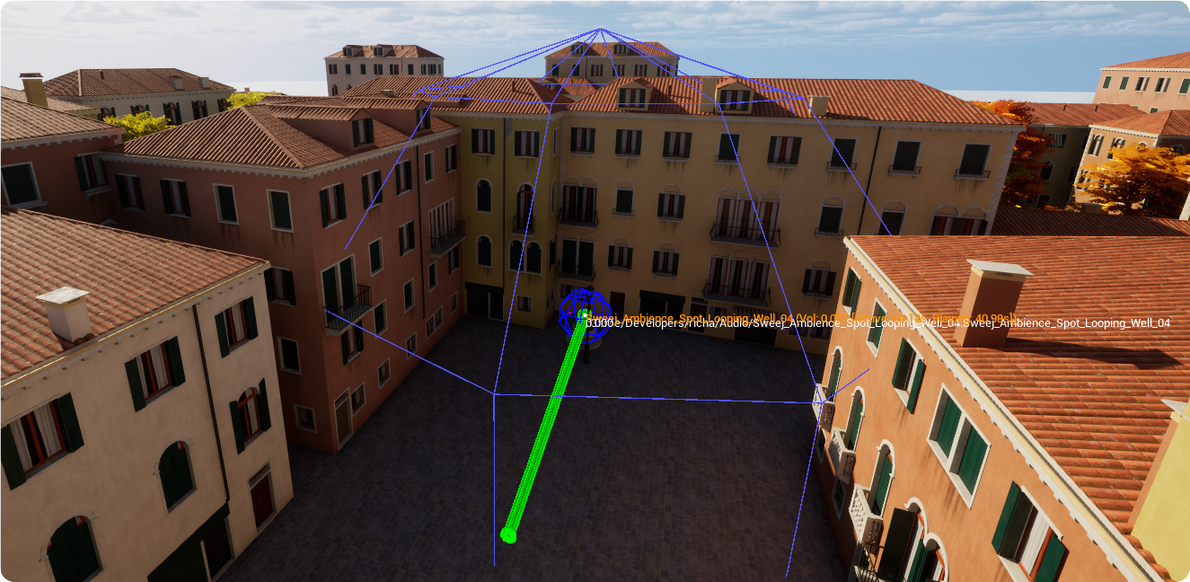
Quick summary of system
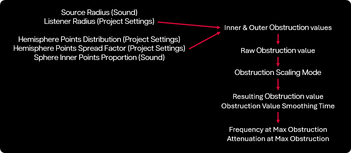
Obstruction values are derived from the number of unobstructed rays between corresponding positions on source and listener hemispheres. These are impacted by user settings which can determine the radius of the source and listener hemispheres, the distribution of positions on those hemispheres, and the proportion of those positions considered 'inner' or 'outer' sound positions. The lowest value from either the inner or outer obstruction forms the raw obstruction value. This value is then mapped to a given range and scaled before being used to apply filtering and attenuation to the sound source.
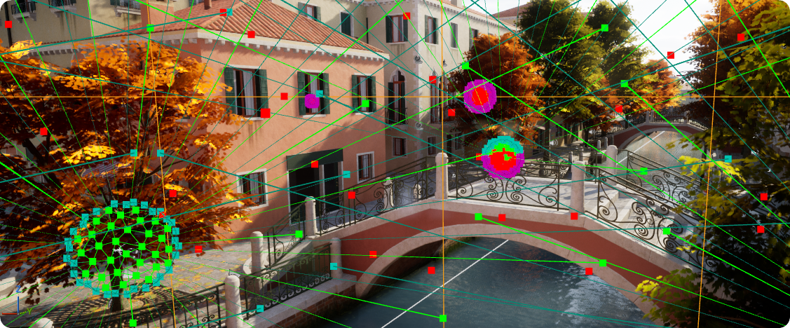
Spheres, positions, and Rays
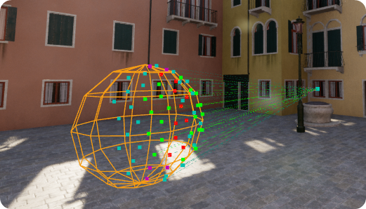
Each sound source has a Source Radius which you can define per actor, and rays are cast between this and the listener sphere, the radius of which is defined in the Project Settings. Sound Positions are distributed evenly on the source and listener spheres using a Fibonacci sphere algorithm. Rays are sent between corresponding points on the two facing hemispheres of the sound source sphere and listener sphere, and the Obstruction Value is determined by the number of successful rays that have not been obstructed. (There is actually a further level of refinement to this discussed in the Inner & Outer sound positions section below.)
64 Sound Positions on the sound source hemisphere and 64 corresponding Listener Positions on the listener hemisphere are used and the Obstruction value is derived using the calculation:
1 -- (No. of successful Traces / 64)
A completely unobstructed scenario would lead to an Obstruction value of 0.0. (Green and Teal colored sound positions illustrate unobstructed paths).
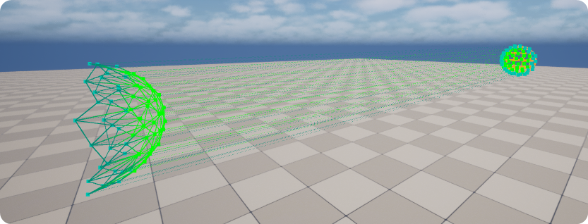
And a 50% obstructed scenario would lead to an obstruction value of 0.5. (Red and Purple colored sound positions illustrate obstructed paths).
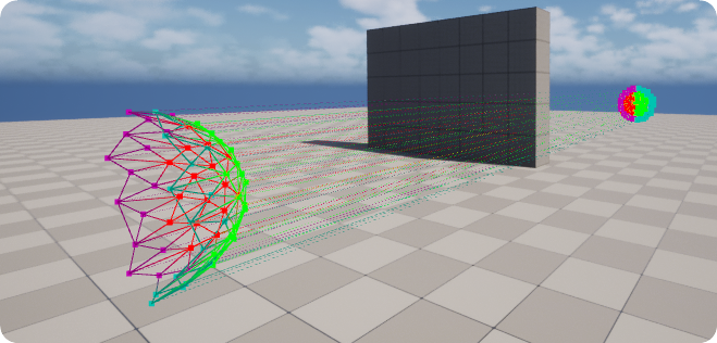
This approach means that even when using sounds with a small source radius it is unlikely that they will ever be fully obstructed by thin obstacles, giving a more realistic result.
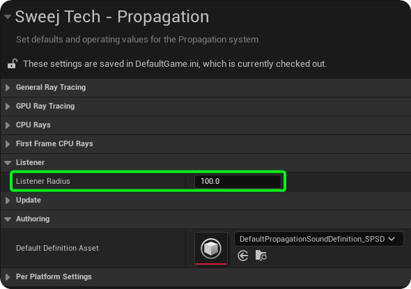
The Listener Radius is set by default to 100 units. This can be adjusted in Project Settings → SweejTech /→ Propagation → Listener. Smaller values will provide more accurate results, but may result in false positives when geometry is close to the listener. Larger values will be less accurate but will offer smoother results.
Hemisphere Points Distribution
The default even distribution of points on the source and listener hemispheres works well in many cases but depending on the nature of your project you may want to experiment with their distribution. You can do this on a project level by adjusting the following values via Project settings → Sweej Tech → Propagation → General Ray Tracing.
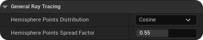
Hemisphere Points Distribution: This determines which distribution (Cosine or Uniform) is used for Fibonacci-generated hemisphere ray source positions. The default is a cosine distribution but you may find that a uniform distribution, that creates a lower density of points in the center, is more suited to your particular needs.
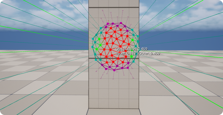
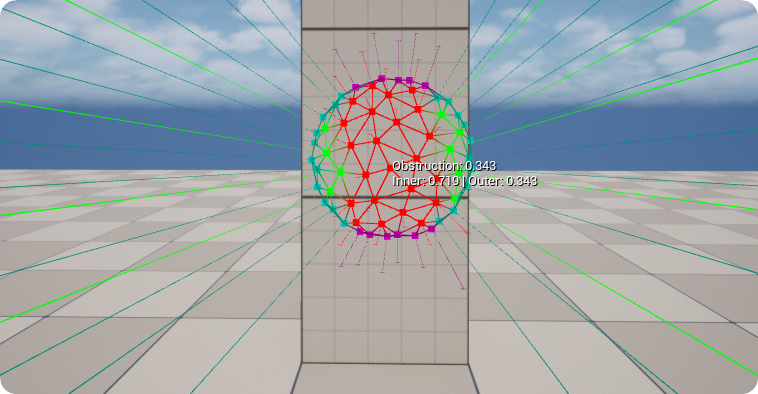
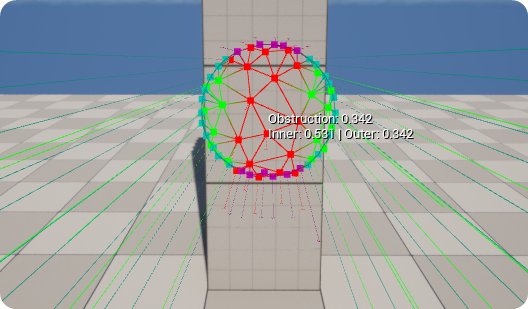
In order to have the opposite effect to the cosine distribution, so that the placement on the points is biased towards the outer edges of the sphere, you can use the Hemisphere Points Spread Factor, this is a nomalized weighting for Fibonacci-generated hemisphere ray source positions. A value of 0.5 reproduces the default behaviour. Values above 0.5 bias points toward the center, Values below 0.5 bias points toward the rim.
Hemisphere Points Spread Factor 0.35
Inner & Outer Sound Positions
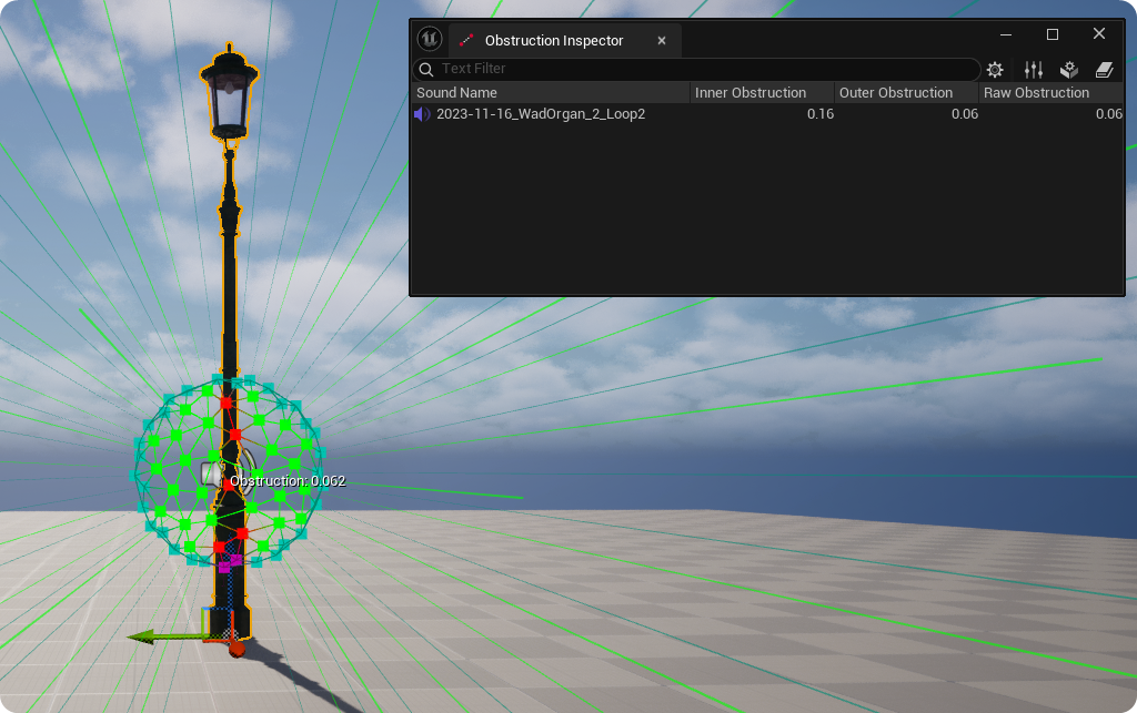
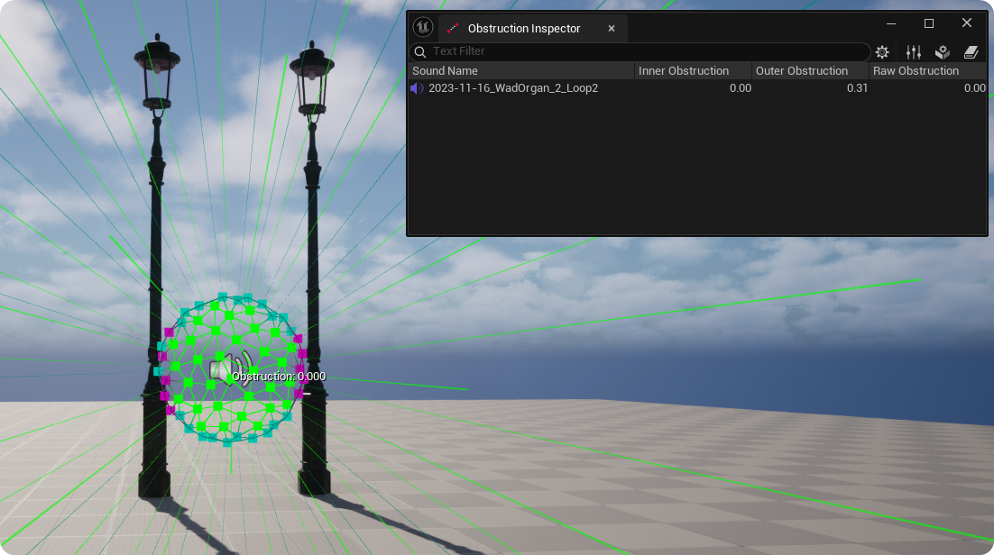
In order to get more consistent, natural feeling results the Sound Positions on the sound source hemisphere are actually considered as two types; Outer positions on the circumference of the hemisphere, and Inner positions within the hemisphere. These values can be displayed in the Obstruction Inspector, together with the resulting Raw Obstruction value which takes the lowest of the two values, in other words the less obstructed path wins.
This approach produces more realistic feeling obstruction results when a source is obstructed by a thin object:
Or when sources propagate between objects:
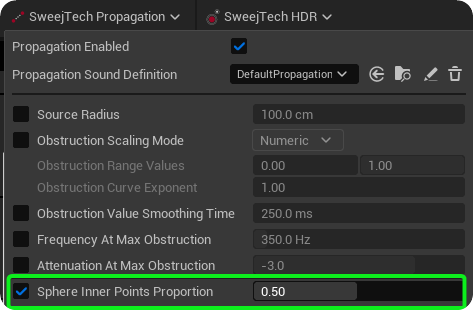
You can also influence the resulting raw obstruction by setting the Sphere Inner Points Proportion on a per actor basis via the Propagation Toolbar. This property controls what proportion of points per sound are considered as the inner part of the sphere.
Frequency, Attenuation and Scaling
Once the Raw Obstruction value has been derived for a sound you have options to determine the attenuation and filter frequency that will be applied to that sound when fully obstructed, what range of obstruction values to map these changes across (Obstruction Scaling Mode and Values), and how quickly these changes will be implemented (Obstruction Value Smoothing Time).
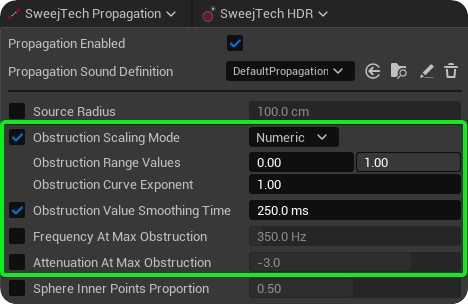
See the Obstruction effects: Frequency, Attenuation & Scaling section within the Authoring pages for details Authoring
Squishy Sound Sphere
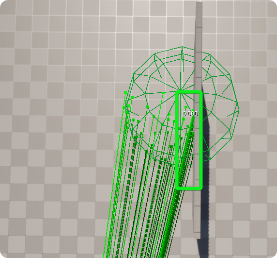
One of the possible issues with the Listener Sphere is that this sphere may overlap with walls or other obstacles when the sound is in close proximity to walls or other obstructions. For example, using a glass -- non-obstructing wall for illustration, the source positions indicated by the red box would ordinarily return as obstructed, even though the path from the listener to the source is clearly unobstructed.
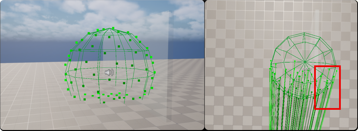
A typical example might be NPC footsteps which are spawned just above at ground level and would always return as nearly 50% obstructed because the path to nearly half of the Source Positions is obstructed by the floor.
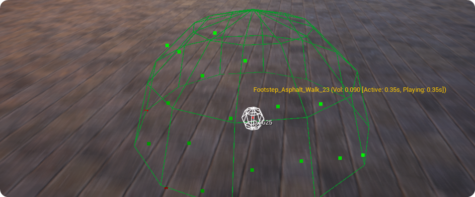
In order to avoid this problem the SweejTech Propagation system makes use of a 'Squishy Ball', where the Source Sphere actually adapts to the geometry around it. In the illustration below you can see that the points that would normally be on the outer surface of the sphere are in fact now originating from the overlapping wall.
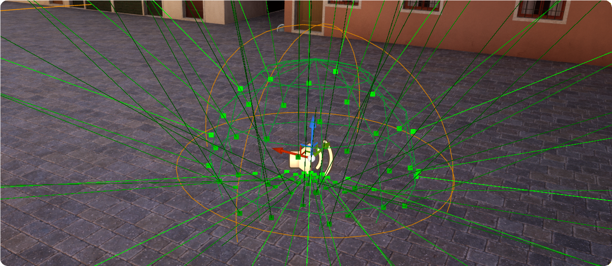
A ray trace on the GPU is made from the sounds origin position to the Sound Positions on the sphere, and if they hit anything then this point is designated as the new sound position. You can see these new Sound Positions clustered on the floor in the illustration below.
First Frame Rays
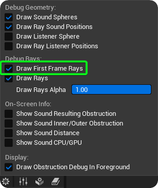
Although tracing and calculations on the GPU are highly efficient, data cannot make the round-trip to and from the GPU quickly enough to apply the appropriate obstruction effect on the first frame at which a sound plays. SweejTech Propagation mitigates this problem by using the CPU to quickly calculate the initial obstruction setting for the first frame. The Num Obstruction First Frame Rays value within Project Settings → SweejTech → Propagation determines how many rays are cast within this first frame on the CPU. The default setting of 3 is sufficient in most cases. You can observe these using the Draw First Frame Rays option from the settings gear icon in the Obstruction Inspector.
These are displayed as a thick red line for obstructed rays and a thick green line for unobstructed rays.
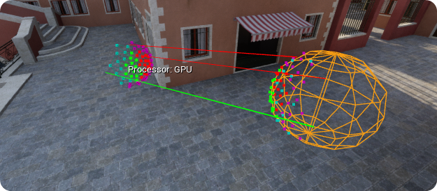
Note: If Obstruction First Frame Arrays is set to 0.0 in the SweejTech Propagation Menu then the Obstruction Value is automatically set to 0.5. This is in order to mitigate sudden jumps from the first frame value to the subsequent value received from the GPU.